Forming a solid
Every activity area starts as a polygon: either drawn in the 3D scene or imported from external data such as feature layers or grade control shapes. To make the area schedulable, the software can convert this polygon into a solid. The solid represents the full 3D volume of material to be mined and is essential for reserving, reporting, and scheduling.
How the solid is created
When you finish drawing or converting an activity area polygon, XECUTE automatically forms the solid using these steps:
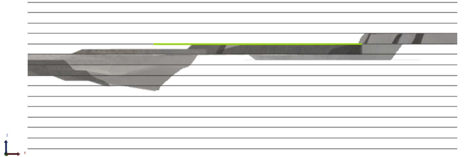
1. Project the polygon to the mining level
The polygon defines the XY footprint of the area.
The software projects this footprint to the assigned mining level, creating the floor of the solid.
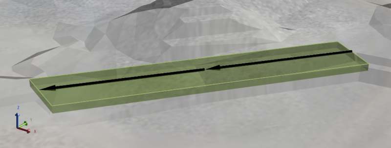
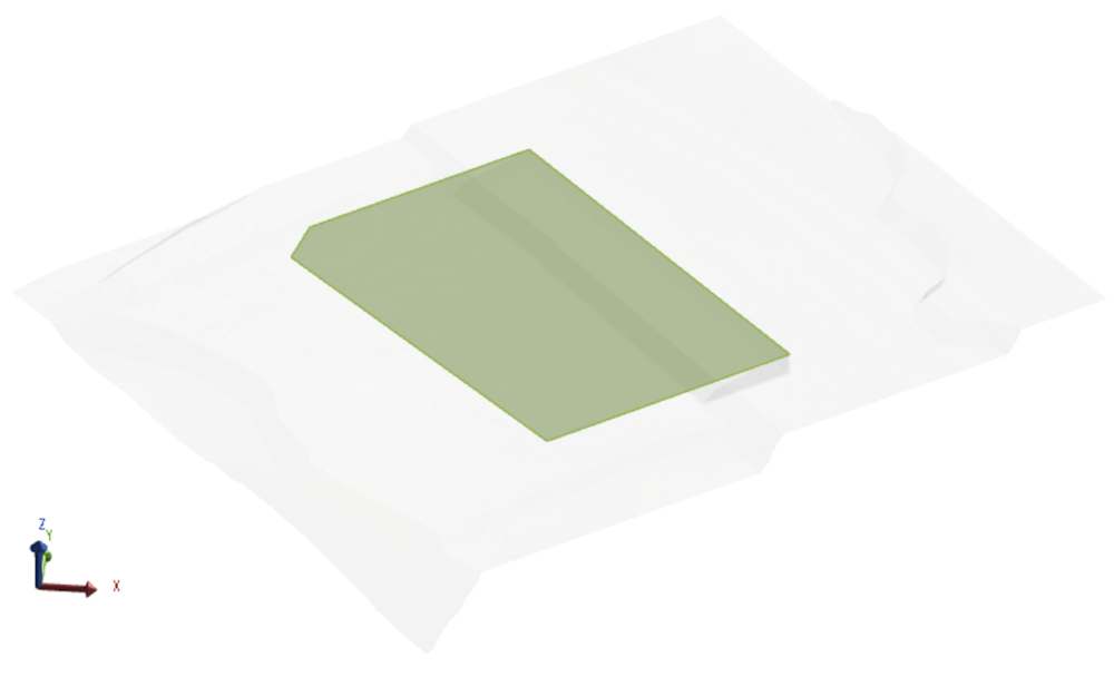
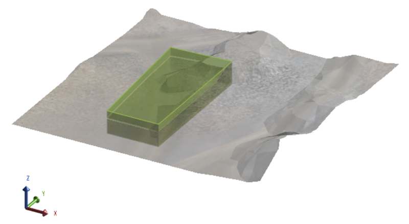
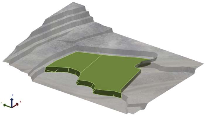
The activity area polygon (green)
Projecting the polygon (green) to a specified mining level (1070) to form the initial solid.
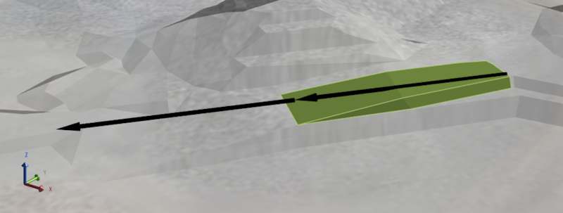
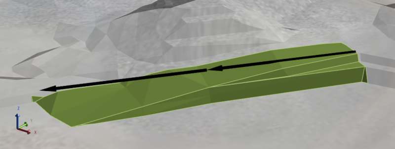
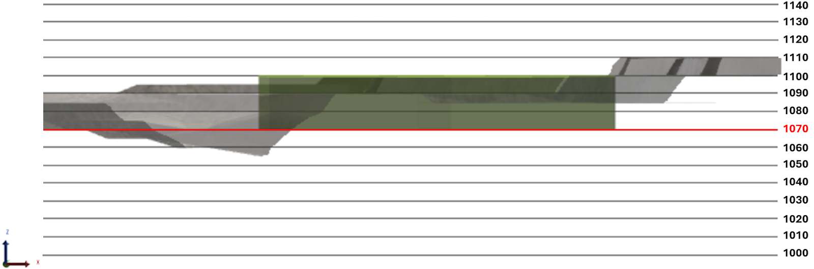
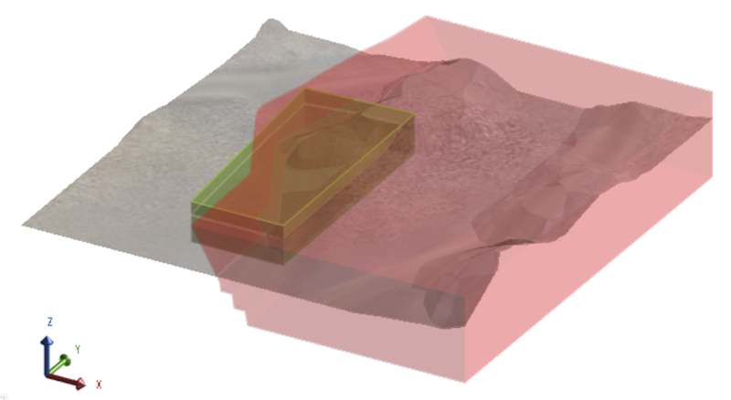
2. Extrude to the topography
The polygon is extruded vertically from the mining level up to the topography. This extrusion defines the roof of the solid and accounts for the actual surface of the mine.
Before and after extruding the polygon to the topography
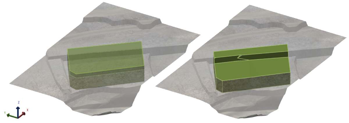
3. Apply trimming rules
The solid is trimmed to respect pit limits. Any portions outside the pit boundary are removed.
Visualising the activity area polygon with and without the pit limit
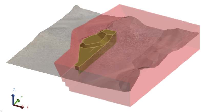

Visualising the activity area solid with and without the pit limit
When drawing activity areas, the software follows the specified overlap rule to control how activity area overlaps are handled. The software can trim the overlap portion from the new activity area or existing activity area – or allow overlaps.
When polygon overlaps are allowed, the software will still trim the new activity area—if both activity areas move material or share the same activity type—to avoid double-counting mineable or the material.
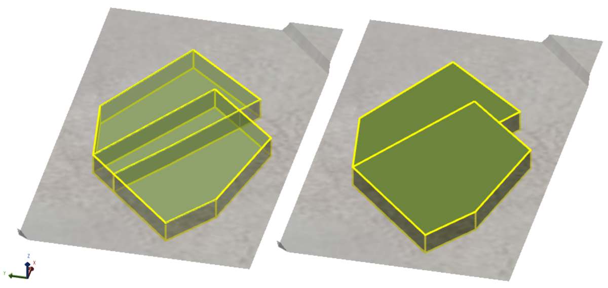
Viewing two activity areas, with the same activity, in their polygonal and solid forms
Troubleshooting activity areas
This section outlines common issues that may occur when drawing or editing activity areas and how to resolve them.
I can’t see the activity area solid
This usually means the solid couldn’t be formed due to invalid geometry or missing inputs.
|
Problem |
Solution |
|---|---|
|
Mining level is above topography |
The activity area’s floor (mining level) must be below the topography to form a solid. If the floor is above the surface, the software cannot project the roof – and no solid is created. Confirm the mining level is below the surface. |
|
The shape is outside the pit limits |
If the polygon is drawn outside the defined pit boundary, the solid is trimmed entirely. You may see nothing, or only a partial shape if part of it intersects the pit. Toggle on pit limits in Scene Manager to check alignment. |
|
The polygon isn’t on the topography |
If the shape is drawn in an area without valid topography, the extrusion fails. Check that the polygon sits on a visible surface. |
You can identify activity areas with no solids by going through the grid on the Activity Areas tab. Invalid or missing solids have a Reserve Status of Error. After selecting the activity area on the grid, you can reconfigure its properties or delete it.
The Reserve Status field can state the reason for the error, such as Mining Level Above Topography.
There is a thin wall between activity area solids
There may be a small wall between adjacent activity areas, evident when they have been scheduled.
After scheduling the activity areas, a small unmined wall between the areas is visible
This occurs when adjacent activity areas don’t share vertices, even if they appear aligned.
The polygons were drawn or edited without snapping to shared points. Even small misalignments can leave narrow gaps between solids, which appear as thin walls in the schedule animation and may affect reporting.
To fix:
-
On the Activity Ares tab, use Polygon display mode and zoom in closely.
-
Drag vertices so they match exactly in XY position.
-
When points align, they turn white – indicating they are shared.
-
Use Wireframe mode to confirm clean joins between areas.
The result of making the activity areas’ walls aligned, removing the thin unmined wall
For more information, refer to Edit Activity Areas.
The activity area solid is partially missing or trimmed unexpectedly
|
Problem |
Solution |
|---|---|
|
Part of the topography goes below the selected mining level. |
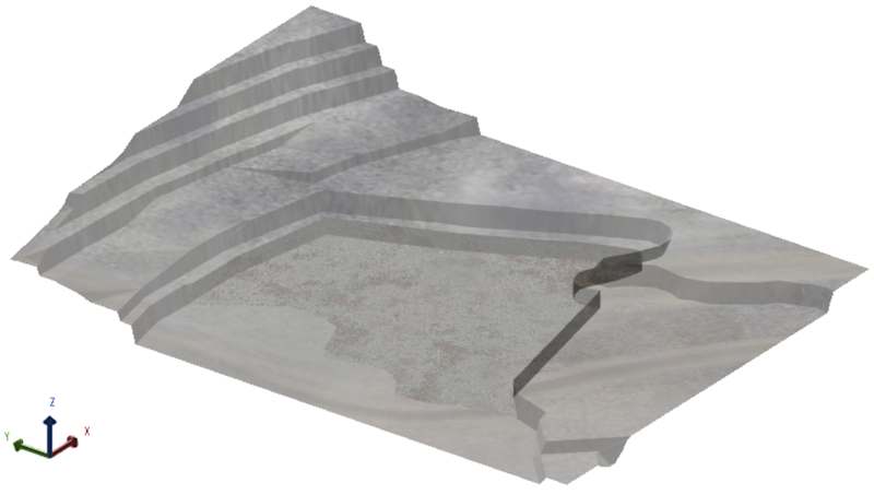
If the activity area isn’t as deep as expected, it’s likely that portions of the polygon floor (mining level) are above the topography. In this case, the solid cannot form in those regions. In this example, the activity area polygon covers a large area:
But the solid doesn’t cover the entire polygon area:
This is because portions of the topography are above the selected mining level. This can be fixed by selecting a lower mining level.
This issue can cause fragmented activity areas that are hard to visually identify.
Before and after fixing an activity area, whose polygon floor was almost entirely above the targeted area of the topography. |
|
The shape is outside the pit limits |
If the polygon is drawn outside the defined pit boundary, the solid is trimmed entirely. You may see nothing, or only a partial shape if part of it intersects the pit. Toggle on pit limits in Scene Manager to check alignment. |
|
Overlap rules remove part of the solid during formation |
Overlap rules control how the software handles intersecting areas during drawing. If both areas move material or share the same activity type, the new area may be trimmed. Review the Overlap setting used during drawing (e.g. Remove from new, Remove from existing, Allow). Redraw the area to avoid unintended trimming. |
|
The area intersects a locked activity area – or one with the same material type |
Locked areas or overlapping areas of the same activity type that move material will trim the new solid during formation. This prevents double-counting material. Check for locked areas in the scene. If needed, unlock the area or adjust the polygon to avoid overlap. Use Solid view to inspect the final geometry. |